 Loading... Please wait...
Currency Displayed in

Categories
- Cables and accessories
- Security Hardware
- Starlink Accessories
- Scanners
- Voice Communications
- Sphero
- Furniture
- Desktop Computers
- Notebooks & Tablets
- Displays & Display Mounts
- Printers
- Storage & Memory
- Power Devices
- Apple
- Audio Products
- Cameras
- Cases & Covers
- Input Devices
- Badgy Plastic ID Cards Printer
- Networking
- Notebook/Tablet Storage
- Point of Sale Equipment
- Ubiquiti
- Projectors
- Software
- Wireless Networking
Related Products
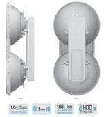


Ubiquiti airFiber 3X (3GHz, 500+Mbps, 200+km) Single Unit

Hover over image to zoom
Product Description
Overview
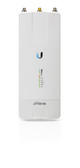
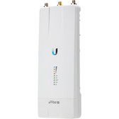
Ubiquiti Networks continues to disrupt the wireless broadband market with revolutionary technology at breakthrough pricing by introducing the airFiber® X, a modular airFiber radio system that will serve a wide range of frequencies and is designed to be compatible with a variety of Ubiquiti® antennas. Building upon the proven design of the airFiber system, the airFiber X allows you to customize airFiber backhaul links or upgrade existing Rocket Point‑to‑Point (PtP) links.
The airFiber X is available in three frequency bands:
• 2.4 GHz, model AF-2X
• 3 GHz, model AF-3X
• 5 GHz, model AF-5X
Engineered for Performance
Ubiquiti’s INVICTUS™ custom silicon and proprietary radio architecture are designed specifically for long-distance, outdoor wireless applications. Our INVICTUS core communications processing
engine surpasses all of the limitations inherent to generic Wi-Fi chips to provide superior performance, long-range capability, DFS flexibility, and higher delivered throughput. The airFiber X features industry‑leading spectral efficiency of up to 17.1 Mbps/MHz, line‑rate data packet processing of up to 525 Mbps of real data throughput, and innovative xtreme Range Technology (xRT™)
for up to 200+ km in range.
Deployment Flexibility
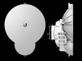
The compact form factor allows the airFiber X to be used with airFiber Slant 45 antennas, or instantly upgrade a 5 GHz Rocket™link that uses a RocketDish™RD‑5G30/RD‑5G34* antenna. The airFiber X supports ± 45° slant polarization for improved noise immunity and Signal‑to‑Noise Ratio (SNR). The compact form factor of the airFiber X allows it to fit into the radio mount of Ubiquiti antennas, so installation requires no special tools.
The airFiber X antennas are purpose-built with 45° slant polarity for seamless integration with the airFiber X.
Carrier Backhaul for the World
Deploy the 2.4, 3, or 5 GHz model that meets your specific spectrum requirements, anywhere around the world. The airFiber X features multiple channel width options to suit your deployment needs – up to 11 different channel sizes available for the AF-2X or AF-3X.
Optimal Operation and Channel Configuration
Channel width flexibility allows you to independently configure TX and RX channel frequencies and place them anywhere within the radio band to avoid local interference. You also have the ability to program different uplink and downlink duty cycles to support asymmetric traffic requirements.
Ultra-Low Latency with HDD Technology
The airFiber X is designed to provide the highest TDD throughput and lowest latency available using proprietary Hybrid Division Duplexing (HDD) technology.
Co-Location
With tower space at a premium, the importance of being able to co -locate equipment is becoming an essential attribute for modern wireless networks. The airFiber X is engineered to permit multiple radios to operate side by side, allowing maximum spectral efficiency.
GPS Synchronization
Precise GPS frame synchronization enables co -located airFiber X radios to transmit and receive data without interfering with each other, enabling better frequency reuse and increased network stability.
Clean Power Output
Using advanced digital signal processing, the innovative airFiber X radio design has an ultra -clean transmitter output, reducing broadband noise, facilitating co -location, and enabling higher -order modulations like 256QAM for greater throughput.
Backhaul
3 GHz
The 3 GHz frequency band offers interference-free operation, enabling the AF-3X to provide a high-reliability backhaul solution, although a license may be required in some regions.
Optimal Operation in Unlicensed Bands
Channel width flexibility* allows independent TX and RX channel frequency configurations anywhere within the radio band to avoid local interference, and the channel centers are selectable in 1 MHz increments. • AF-2X/AF-3X 3.5, 5, 7, 10, 14, 20, 28, 30, 40, 50, or 56 MHz • AF-5X 10, 20, 30, 40, or 50 MHz You also have the ability to program different uplink and downlink duty cycles to support asymmetric traffic requirements.
* Channel widths may vary according to country/region regulations.
| Model | Frequency | Antenna Compatibility |
| AF-3X | 3 GHz | AF-3G26-S45 |
|
AF-3X |
|
|
Dimensions |
224 x 82 x 48 mm (8.82 x 3.23 x 1.89") |
|
Weight |
0.35 kg (0.77 lb) |
|
RF Connectors |
(2) RP-SMA Weatherproof (CH0, CH1) (1) SMA Weatherproof (GPS) |
|
GPS Antenna |
External, Magnetic Base |
|
Power Supply |
24V, 1A PoE Gigabit Adapter (Included) |
|
Power Method |
Passive Power over Ethernet Pins 1, 2, 4, 5 (+) and Pins 7, 8, 3, 6 (-) |
|
Max. Power Consumption |
17W @ Max. Power/Duty Cycle |
|
Supported Voltage Range |
19-29VDC |
|
Mounting |
airFiber X Mount (Rocket Mount Compatible) GPS Pole Mount (Included) |
|
Certifications |
CE, FCC, IC |
|
Operating Temperature |
-40 to 55° C (-40 to 131° F) |
|
AF-3X Networking Interface |
|
|
Data Port |
(1) 10/100/1000 Ethernet Port |
|
Management Port |
(1) 10/100 Ethernet Port |
|
AF-3X System |
|
|
Processor |
INVICTUS IC |
|
Maximum Throughput |
525 Mbps 1 |
|
Maximum Range |
200+ km 1 |
|
Encryption |
128-bit AES |
|
OS |
airOS F |
|
Wireless Modes |
Master/Slave |
|
AF-3X Radio |
|
|
Frequency Range |
3300-3900 MHz (Dependent on Regulatory Region) 2 |
|
Max. Conducted TX Power |
29 dBm2 (Dependent on Regulatory Region) |
|
Frequency Accuracy |
± 2.5 ppm without GPS Synchronization ± 0.2 ppm with GPS Synchronization |
|
Channel Bandwidth |
3.5/5/7/10/14/20/28/30/40/50/56 MHz Selectable3 Programmable Uplink and Downlink Duty Cycles Independently Programmable TX and RX Frequencies |
1 Throughput and range values may vary depending on the environmental conditions.
2 For region-specific details, refer to the Compliance chapter of the airFiber X User Guide at downloads.ubnt.com/airfiber 3 Channel widths may vary according to country/region regulations
|
AF-3X Suggested Max. TX Power |
|
|
8x |
21 - 22 dBm |
|
6x |
23 - 24 dBm |
|
4x |
25 - 26 dBm |
|
2x |
29 dBm |
|
1x |
29 dBm |
|
AF-3X Receive Sensitivity |
||||||
|
Rate |
Modulation |
Sensitivity (10 MHz) |
Sensitivity (20 MHz) |
Sensitivity (30 MHz) |
Sensitivity (40 MHz) |
Sensitivity (50 MHz) |
|
8x |
256QAM MIMO |
-66 dBm |
-64 dBm |
-62 dBm |
-61 dBm |
-60 dBm |
|
6x |
64QAM MIMO |
-74 dBm |
-71 dBm |
-69 dBm |
-68 dBm |
-67 dBm |
|
4x |
16QAM MIMO |
-81 dBm |
-78 dBm |
-76 dBm |
-75 dBm |
-74 dBm |
|
2x |
QPSK MIMO |
-88 dBm |
-85 dBm |
-83 dBm |
-82 dBm |
-81 dBm |
|
1x |
½ Rate QPSK xRT |
-90 dBm |
-87 dBm |
-85 dBm |
-84 dBm |
-83 dBm |
Warranty Information
1 Year Warranty